Cadence Schematics Capture CIS - Component Information System
Article published Feb 10th 2023!
In order to work efficiently on hardware designs, it's critical an inventory or database of commonly used components be readily available. For manufacturing purposes, the assembly house will typically source parts as needed and this shouldn't be of concern to the designer. Rather, the designer would benefit from maintaining an electronic inventory which not only includes specific parts but also conveniently categorizes them for ease of searching and future use. Key component parameters should be clearly documented for quick reference. As an example, for ceramic capacitors the following parameters would most likely be of interest when designing the schematic circuitry.
The designer may be interested in having additional attributes visible which can also be included. The default component database provided as part of the Cadence Schematic Capture CIS installation features an abundance of parameters even including a link to the actual datasheet of the component. There is indeed effort involved in maintaining a component database but the benefits are quickly realized when attempting to utilize a part with specific parameters which can be quickly searchable. The Query feature or even the sorting method within the table makes the selection task significantly easier. The capacitor table has been arranged to show all ceramic types which are rated up to 50V. Double clicking on the row of interest will select the component and allow the user to place it on the schematic canvas.

Database Connectivity Overview
Enabling a database with the list of components along with their relevant parameters is supported within Cadence Schematics Capture CIS. Many formats are accepted by the tool and depending on the complexity, the appropriate database type will make sense. Microsoft Access is a powerful tool for creating databases with explicit control of the data types used for each entry. Excel sheets are also another popular format for smaller databases whereas a SQL server is sometimes utilized for hosting large dynamic information structures. Each method brings it's own benefits and challenges. In terms of challenges, Cadence Schematic Capture CIS is somewhat particular about the data types of these entries and also certain properties are mandatory which must be part of the component database in order for it to be accepted. The built-in wizard does an excellent job of guiding one thru the setup process but can also be frustrating for a new user. The example illustrated below can be referenced to alleviate a number of shortcomings of the wizard and better assist in the initialization process. As a high-level overview, for a successful setup of a component database, there are four key ingredients and associated steps which are required:

Component Database
As mentioned earlier, a database can exist in several different formats but in terms of the information that is captured, it will be a table or tables comprising of the component parameter and it's respective value. Microsoft Access is well recognized in the industry as a database tool which is shown below in this example.

A separate table is created for each component category and within the table, the columns are used indicating the parameters. As a new part is added to the row, the various parameter fields are updated. The data type specified for each field is of importance as it may restrict user input and further have some conflicts when attempting to integrate with Orcad CIS. The recommendation is to set as "String" type or "Text" in the case of Microsoft Access for maximum flexibility.
Open Database Connectivity (ODBC)
In order to allow applications to interface with databases, Microsoft has enabled the ODBC tool for improved compatibility. Basically, the ODBC driver acts as a translator and is used to pass queries from the application to the database management system (DBMS). In this case, the application is OrCAD Capture CIS, the ODBC driver will be configured in Windows as shown below, and the DBMS is Microsoft Access.


CIS Configuration File (.DBC)
The Database Configuration file specifies the mapping of the database parameters to the CIS parameters. The Setup Wizard does a thorough job of walking thru the various steps involved and can be initiated from the Options menu bar and then selecting "CIS Configuration...". A new window will appear on which selecting "New" will initiate the Setup Wizard.

You have the option of following the various prompts and selecting the appropriate items as you navigate the process or upon identifying the correct database and selecting the tables of interest, you can click Finish which will take you to the final review window. The same items covered thru the wizard flow will be visible that can be edited as desired.

At a minimum OrCAD CIS requires the following properties to be mapped: Part_Number, Part_Type, and Schematic_Part. Without these, the component will not be able to be used in the design. Other checkboxes in the columns can be selected as desired based on the usage model. For example, if Browsable is selected for a specific property, it will format that field into a link so it can be clicked within the CIS table. This is a convenient feature to allow quick access to a component datasheet. Enabling the checkbox in the column Transfer to Design will allow the user to display the property on the schematic page when that particular component is placed. Having parameters such as Value and Voltage displayed is a common industry practise.
Utilizing the Component Database
Once all the previous steps have been completed successfully, we are now in a position to actually begin using the component database. Open a new schematic sheet and use the shortcut key "Z" on the keyboard or select Place -> Database Part from the menu bar. A new tabbed window will appear with the database linked as per the configuration settings. Expanding the items will list out the individual tables and also the subcategory based on the Part_Type parameter. A single click on a particular part will display it's properties and a double-click will allow the user to place the schematic symbol on the design sheet. The columns in the CIS table can be sorted as desired to help in part selection or a more sophisticated method is to use the built-in Query feature. Several properties can be searched in parallel to quickly expose a part that is best suited based on the requirements.

Summary
Despite the numerous steps involved in setting up OrCAD CIS to utilize an external component database, the efforts are well worth it. The convenience in selecting a part from inventory is realized not only during the design phase but these benefits carry over to the task of BOM generation as well. The same component properties can be added to the BOM which is helpful both during the review process but also for the assembly house when any issues arise such as part shortages where replacements need to be identified. The intuitive and user-friendly CIS interface makes the task of component selection significantly easier and is highly encouraged for teams who intend to deploy several designs with multiple users working in parallel.
Component Placement
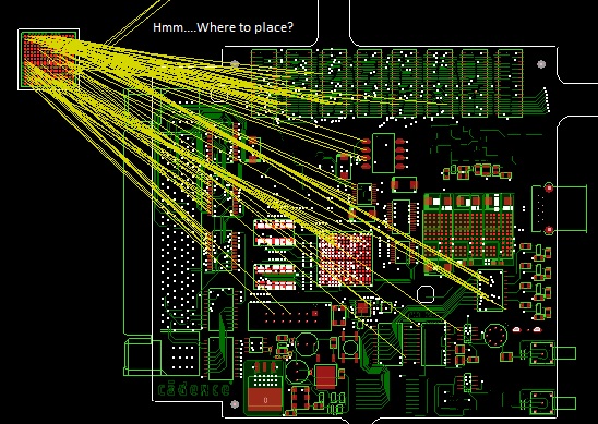
Careful placement of components is critical to a successful design
Schematic Capture
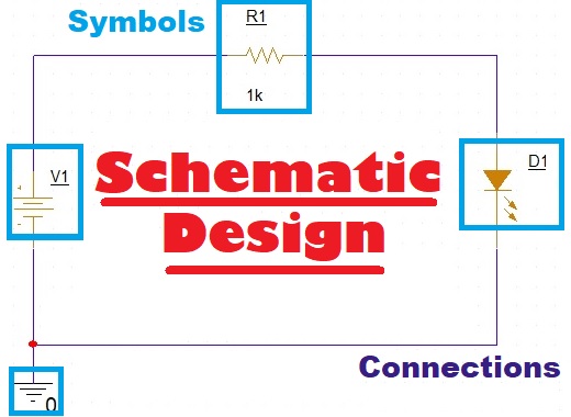
Creating schematic symbols, drawing the circuit, and generating the netlist
Generate Gerbers