Trace Length Matching
Article published March 22nd 2023!
High speed signal routing already has complexities around maintaining impedance constraints both in the design and also fabrication yet another item which needs attention is the signal propagation speed. This task is simplified in Cadence Allegro PCB Editor with the use of the High Speed Trace Tuning feature.
Parallel Bus Trace Length Matching
For parallel busses, it is critical that respective data bit signal traces are routed within a few millimetres of each other. The specific length and timing constraint is dependent on the interface as well as the end-to-end requirements. There may be additional constraints with respect to the clock or strobe signals that need to be considered as well. The Constraint Manager is capable of capturing all these requirements and providing live feedback during signal routing. The example below illustrates a 4-bit bus on the DDR3 DRAM interconnect. The data bits DQ0, DQ1, DQ2, and DQ3 are all set up to be within 0.01ns of each other. In order to create this Electrical Constraint Set, the SigExplorer tool needs to be opened for a given topology and the parameters need to be defined. Once it is done for a single PinPair, it can then be carried to the rest of the signals within the Bus or Class.

Make sure the relative propagation constraint set which has been created in SigExplorer is pushed to the Constraint Manager. This can be confirmed by reviewing the Electrical section in the Constraint Manager and expanding All Constraints to select the User Defined. The Worksheet will list all of the custom electrical constraint sets which have been created.

The next step will be to map this newly created Electrical Constraint Set to the rest of the DRAM signals within this grouping. Navigate to the "Net" subsection in any of the Constraint Manager worksheets and find the 4 DRAM signals of interest. Highlight them all and right-click to select Create Class. A new group will appear towards the top of the worksheet for which the Electrical Constraint Set (ECS) that was recently created can be referenced. Immediately upon mapping this Net Class to the ECS, a Match Group will be visible on the same worksheet towards the top. The four DQ signals will be listed with their PinPair connections clearly visible. It's worthwhile to confirm the connections are as per expectations within the same packages but different pins.

Before proceeding to the routing of these signals on the printed circuit board it's recommended to also account for internal package connections. The package bond wire trace lengths can be captured in a Pin Delay file provided by the package vendor. This Pin Delay file can be imported in the Allegro PCB Editor Constraint Manager and used for complete length matching assessement.

Now that all the key ingredients are available, the design engineer can begin the task of routing these high speed signals. Unless explicitly defined, the tool will arbitarily assign one of the nets as the "Target" and all other nets within the Match Group will be expected to be routed within the tolerance specified. In this particular example, DQ2 is the Target and DQ0, DQ1, and DQ3 must be length matched based on the routed length of DQ2. The length of the signals are visible in the Constraint Manager worksheet along with the converted timing value based on the propagation velocity factor and routing layers. In the example below, we can see that the DQ0 trace length is significantly shorter than the target signal DQ2.

In order to fix this error, the designer needs to deliberately lengthen the trace routing. A quick way to navigate to the trace is to right-click the row in the Constraint Manager worksheet and click Select and Show Element. The respective trace should become highlighted and properties associated with the net will be displayed. The Delay Tune feature is a convenient method to adjust the trace length. Multiple options are available for creating extensions in the form of accordions, trombones, or sawtooth styles. The specific gaps and width dimensions can also be fined controlled. Once a desired style has been selected, the trace can be edited and a live tuning indicator becomes visible giving real-time guidance on the length matching. The goal is to ensure the indicator becomes green with ample margin on both sides.

Confirming the modifications are captured in the Constraint Manager, we can see the timing constraints are no longer being violated and DQ0 is now within the tolerance specified. Another approach of course would have been to reduce the length of DQ2 to match DQ0 but then DQ1 and DQ3 would also need adjustment. In dense designs, the task of completing routing is difficult already and with the additional burden of length-matching for high speed busses, this becomes an art which requires out-of-the-box thinking.

Differential Trace Length Matching
For differential traces, the positive signal and negative signal also need to be length matched. The Constraint Manager has the capability to monitor this requirement as set by the user and report any violations by issuing a DRC marker. The various industry standard specifications have their own intra-pair matching requirements and as an example, we can look at the PCIe CEM spec to understand what constraints should be fed into the EDA tool. For differential traces, the standard defines intra-pair skew must be less than 2.5 mil for the Add in Card and less than 5 mil for the system board. Once again, the delay tune feature in Allegro PCB Editor gives live feedback to the user as they are modifying the design.

Rather, for ideal routing of differential traces, dynamic phase matching is preferred which means the two traces are adjusted with respect to each other as soon as a length deviation occurs. Upon bends, the outer trace traverses a longer distance therefore either an immediate opposite direction turn should be made or the inner trace should be adjusted and lengthened accordingly. The end to end length matching is often referred to as static phase matching and it's common to see the tuning happen only at either end of the trace routing. The constraint manager in Allegro PCB Editor can be used to set up both dynamic and static phase matching to ensure ideal differential trace routing.

Summary
High speed signal routing has numerous challenges one of which is to ensure the trace lengths are within a certain range of each other. The designer must be mindful of these constraints and set them up accordingly to ensure the design works as expected. Both the single ended signals and the differential signals have certain requirements which must be captured correctly and prior to the routing effort. Post-route modifications is a near impossible task in dense designs where stack up layer count is limited and impedance control is necessary which further limits options for adjusting traces to meet tuning requirements. Despite this being a difficult task, it is quite satisfying once all constraints are met and the analysis confirms compliance by marking each cell green! Happy length matching!
Component Placement
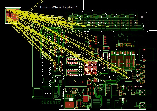
Careful placement of components is critical to a successful design
Schematic Capture

Creating schematic symbols, drawing the circuit, and generating the netlist
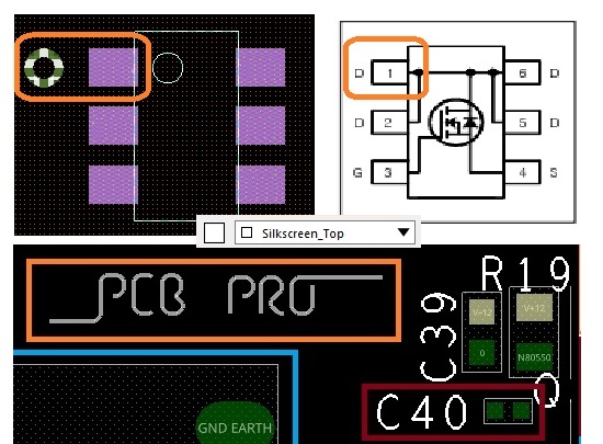
Silkscreen Markings