Colour Selection in Allegro PCB Editor
Article published Dec 13th 2022!
Managing an abundance of nets, shapes, traces, on a multi-layer stackup is bound to get anyone confused on how to differentiate between all these objects. Thankfully Allegro PCB Editor allows the user to set up unique colour profiles for each object and layer which makes this task significantly easier. The most efficient method is to open the Colour Dialog and specify the colours as desired all in one location. This is also a very convenient method to review the various Classes and Subclasses in the design. The Colour Dialog can be accessed by the shortcon icon on the toolbar or from the Display Menu drop-down and Colour/Visibility.
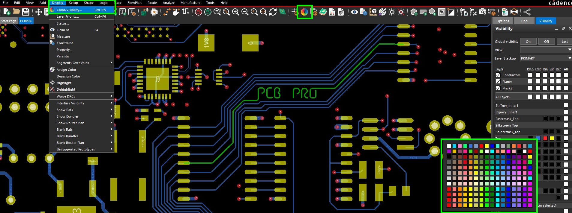
Another efficient method to make an immediate colour change to a particular object or layer is to simply perform a right-click. If you right-click on a colour square, most likely a colour palette will open up and you have the freedom to change the colour as you wish. Otherwise, if you are right-clicking on an object, you may be presented with a menu which may have an Assign Colour option. A similar colour palette window will open allowing you to select the new colour.
Colour Dialog
The one stop shop for assigning colours is the Colour Dialog which opens in a new window and provides an intuitive interface to navigate across all layers and object types. As the colour mapping is being edited, the user has the option to quickly make the respective change visible to confirm if it aligns with their vision. Multiple layers/objects can be quickly assigned layers by first selecting a colour and then clicking the square on a given row or coloumn. All items in that category will be updated to the colour selected. If the checkbox is selected, a tick will appear indicating the layer or object is visible. Removing the check will disable the visibility for that particular feature. Additional options exist in the Colour Dialog window in the Display tab where the user can modulate the shadow and transparency characterisitcs. Other configurations that can be customized include the visibility pane itself which typically appears on the right side of the screen in Allegro PCB Editors default setup. The list of layers and visible classes can be adjusted as desired.
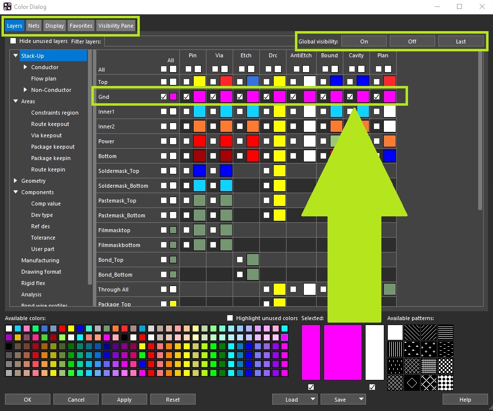
Once satisfied with the customization, the user can apply the changes to the current design and most importantly, save these settings and export them so they can be reused in other designs. A consistent and configurable working environment is valued by many and fortunately Allegro PCB Editor offers that comfort in this regard. Upon clicking the Save button, a drop-down list will appear giving the user several options.
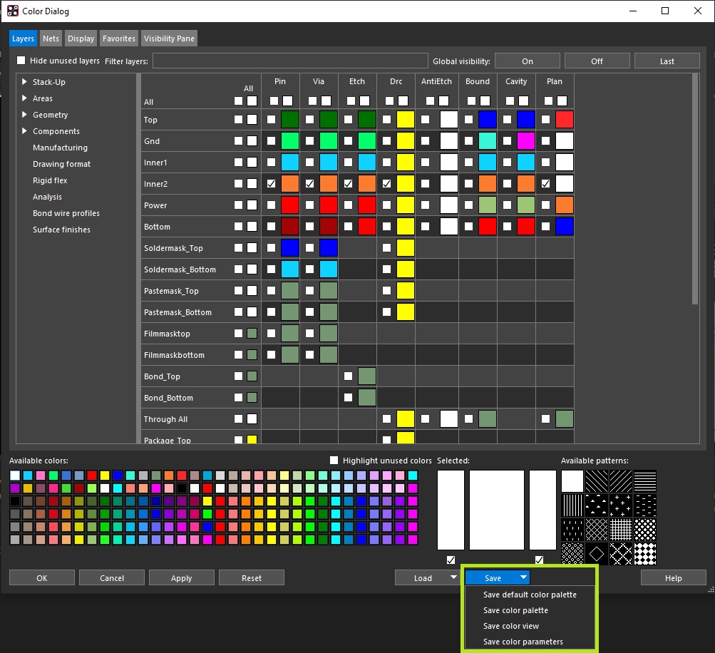
Save Color Palette
This method saves the colour settings as selected in the Colour Palette. It's a great feature to be able to specify certain colour schemes covering all relevant layers and objects in a design and carry them into a new project. Having this consistency allows the designer to have an intuitive feel when they are routing the board and traversing across the stackup layers. A .col format file can be saved and loaded in a new design as desired.
Save Color View
If a specific view is required then the Colour View option is recommended. This will quickly enable the Classes and Subclasses along with the zoom level (if desired) once the file is loaded from the Colour Dialog. In addition, the View dropdown from the Visibility pane will indicate the . color filename that can be selected to quickly enable the saved view. This is a convenient method during review sessions to quickly highlight certain layers/features in the design instead of fumbling thru enabling these items. Typically film views are added to the dropdown list by default once these are setup as part of the artwork generation content. For the cases where films are not required but only a view is needed, this is the method that should be pursued.
Save Color Parameters
This method allows for a more comprehensive configuration save which extends beyond just the colour scheme or view mode. The .prm file allows for the user to select features that they would like to replicate in a new design environment. The following table hightlights the various options that can be selected as part of the Save Color Parameters feature.
| Design Setting | Global values and grid settings |
| Artwork | Artwork film definitions |
| Color Layer | Priority in which layers are drawn |
| Color Palette | Color parameters and color table |
| Color Component | Custom color for symbol instance of the component |
| Color Profile | Custom color for wire profile group |
| Color Net | Net custom color and states. When a file containing net color data is imported into any design, only the nets that exist in that design are read; the rest are ignored. Net color assignments are not overwritten, but rather incremented. To completely replace net color assignments, click Clear All Nets in the Nets section of the Color dialog box before importing a file containing net color data. |
| Text Size | Text size settings |
Summary
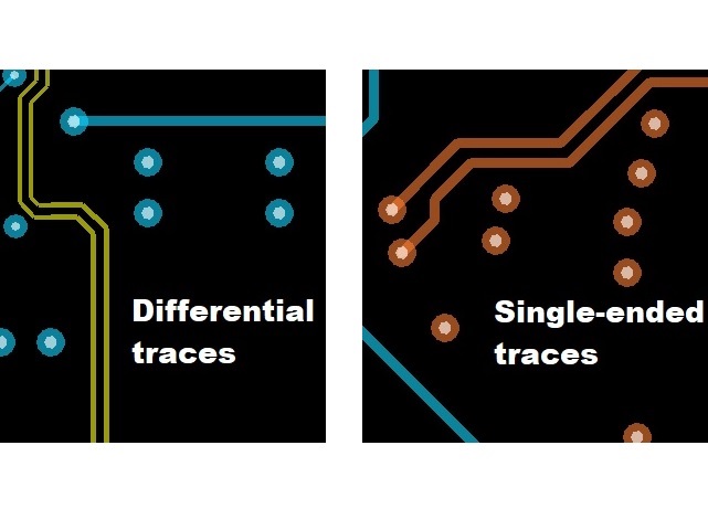
Color features are great! They provide the customization to allow more efficient and intuitive layout work. Setting a net colour and being and to visualize the trace topology as it traverses thru the layers without having to toggle layers is a huge time saver. Or if colours are set on a per layer basis, clearly identifying which layer a particular object is on is also just as beneficial. It really comes down to personal preference and the fact that Allegro PCB Editor allows for customization freedom is a huge motivating factor to take the time to personalize these features and then save them for re-use. If a common color scheme is defined and used across multiple users, it increases efficiency during review sessions as the most common questions such as "which layer are we on?" or "what trace is this?" can be avoided!
Watch Demo! - Like & Subscribe!
Routing Traces
Diligent routing is critical to ensure a successful design
Shapes
Pour large regions of copper in your design using shapes
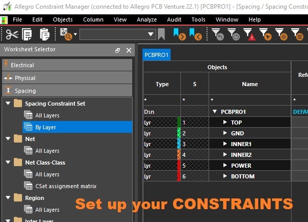
Constraint Manager