Sub-Drawing Feature in Allegro PCB Editor
Article published Nov 16th 2022!
A unique and powerful feature within Allegro PCB Editor worth sharing with users of this EDA tool is the Sub-Drawing functionality. This is essentially a copy and paste mechanism that allows design features to be transferred across .brd files. There are a few steps involved which need careful attention but once completed successfully, the result is very much worth it. If an existing design has a section that needs to be copied over to a new design, the Sub-Drawing export/import method is extremely efficient.
There are a few things that are worth mentioning to ensure there are minimal frustrations with this effort:
Depending on the content that is desired to be copied over, the appropriate items must be selected at the time of export. If only component placement needs to be preserved and not trace routing or shapes are to be copied over, then they should not be selected. If in the case they are to be copied over, then an option exists as to whether the net connectivity should carry over as well or not. These selections become visible when the Sub-Drawing export is initiated. The user will see the Options tab visible and be prompted to select items of interest.

The Object Find Filter can be used to select objects of interst and then picked on the design canvas. A box can be drawn to capture multiple items at a time before a prompt to select the origin point is needed. This is useful if the placement in the new design needs to align to a particular reference point. There is however one frustration with this feature which is that the user cannot add or remove to their object selection prior to exporting. Essentially, all objects should be visible and selected in one single iteration.

As seen in the example above, the ASIC and all of it's decoupling capacitors and strapping resistors are intended to be copied over from the original design to a new design. This is a great feature for derivative or iterative designs where the complex components such as the ASIC or SoC are common. It offers a significant time and effort saving to have to complete redundant work and allows a proven layout to be re-used. Keeping in mind some the key points mentioned above, importing the Sub-Drawing is relatively easy. Upon selecting the .cpl file of interest, the user is simply prompted to select the pick point at which they wish to paste the contents. The snap feature is available allowing precise placement as needed. Depending on how carefully objects were selected upon export, there may or may not be any clean-up required when objects are pasted in the new design.

Summary
Regardless of which approach was pursued, it definitely beats having to begin the placement and routing from scratch! One may also wonder why not just rename and save the original design and then import the new netlist. This is also a reasonable approach but now the user needs to spend time carefully cleaning up content that is not relevant. Removing objects from the canvas may be straight forward but don't forget about the constraint manager, via structures, artwork films, fab notes, drill table...need I go on? Sometimes, it's just easier to start on a clean design and only copy/paste contents of interest. For that, now you know how!
Z-Copy
Best kept secret in Allegro PCB Editor for copying shapes across layers
Thermal Relief

Pour large regions of copper in your design using shapes
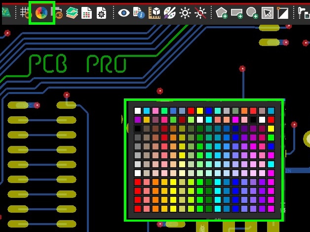
Color Settings